
Home, Auto Repair Library, Auto Parts, Accessories, Tools, Manuals & Books, Car BLOG, Links, Index

Cars and light trucks have extensive electrical systems with lots of wiring and hundreds of circuits. An electrical circuit is basically a route or path through which electrons flow. An electrical circuit must form a complete loop so the current will continue to flow. The electrons need a return path back to their source (the battery or alternator) otherwise they have no place to go.
There are essentially two kinds of automotive electrical circuits:
* A series circuit is one in which all the circuit elements are connected end-to-end in chain-like fashion.
The current has only one path to follow so the amount of current passing through it will be the same throughout. The
total resistance in a series circuit is equal to the sum of the individual resistances within each circuit element. If one
element in a series circuit goes bad, continuity is broken and the entire circuit goes dead because the current cannot complete
its journey through the circuit.
* A parallel circuit is one in which circuit elements are connected next to or parallel to one another. This
creates multiple branches or pathways through which current can flow. The resistance in any given branch will determine the
voltage drop and current flow through that branch and that branch alone. One of the advantages of a parallel circuit is that the
various segments or pathways of the circuit can operate independently of one another. If one element goes open (breaks
continuity), it won't disrupt the function of the other.
Some circuits combines elements of both a series and parallel circuit. These would be called a series-parallel electrical circuit. In this type of circuit, part of the circuit might have loads in series while in another part the loads would be parallel.

Troubleshooting automotive electrical circuits often requires measuring volts, amps or ohms. These are three basic units of measurement that are used to describe what goes on inside an electrical circuit.
Voltage is the difference in electrical potential between two points, or the amount of "push" that makes the electrons flow. It's also called the Electromotive Force (EMF). It is like the pressure that forces compressed air through a hose, but instead of being measured in pounds per square inch, voltage is measured in units called Volts.
You can measure volts with a digital or analog voltmeter. For late model vehicles, a digital voltmeter is recommended because the voltage levels you are measuring often have to be read down to tenths of a volt (0.1 volt).
All passenger car and light truck electrical systems are 12 volts and have been since the mid-1950s. The electrical systems are all Negative (-) ground, with the body usually serving as the ground connection for many electrical circuits. The battery negative cable is attached to the metal body or chassis, while the positive battery cable (+) is connected to the power side of the vehicle's electrical circuits and charging system.
Many sensors and sensor circuits use a lower voltage, typically 5 volts, while the ignition coils generate a very high voltage (5,000 to 35,000 volts) to fire the spark plugs. Hybrid vehicles use a high voltage (140 to 300 volt) battery, generator and electrical motor for their stop-start systems and electric drive.

Use extreme caution when working around hybrid electrical components (which are usually color coded ORANGE, and avoid making contact with the ignition coils or spark plug wires when your engine is running to reduce the risk of being shocked. A shock from a spark plug wire can be painful, but not fatal because the current (amperage) is low. But a shock from a hybrid battery can be fatal!
Current is the amount or volume of electrons that flow through a conductor or a circuit. It is a measure of volume, and is specified in units called amperes or amps. The analogy with an air hose would be the number of cubic feet per minute of air passing through the hose. One amp is equal to 6.3 million trillion electrons (6.3 with 18 zeros after it) flowing past a point in one second! That's a lot of electrons, but a relatively small current in many automotive circuits. A starter, for example, can draw several hundred amps while cranking the engine.
Amps are measured with an ammeter, or a multimeter that has an amp function. Measuring amps usually requires using an inductive pickup that is clamped around a wire to measure the current flowing through it, though very small currents (100 milliamps or less) can often be measured directly through the meter itself without having to use an inductive pickup.
Fuses are used to protect electrical circuits from dangerous overloads that could cause them to overheat, melt or catch fire.
Fuses are rated according to how many amps they can handle before the fuse blows and stops the flow of current
through the circuit. A blown fuse, therefore, is often an indication of an overloaded circuit or a fault
such as a short that is causing excessive current flow in the circuit.
For more information, see the related article on Power Centers: Relays & Fuses

Caution: If a fuse has blown, replace it one that has the SAME amp rating as the original. DO NOT substitute a replacement fuse with a higher amp rating as this may allow the circuit to overheat or suffer damage. And NEVER replace a blown fuse with a solid wire or conductor as this will prove no overload protection at all.
Electrical resistance is the opposition to the flow of current, or the restriction that impedes the flow of electrons. Resistance is measured in units called ohms. The flow of air though a hose can be reduced by pinching it, by reducing the diameter of the hose or by holding your finger over the outlet. Likewise, current flow through a wire can be slowed or controlled by adding resistance. Resistance can be created by altering the composition of the material, by decreasing the size of the conductor or wire (smaller wire has more resistance than larger wire), or by adding heat (heat increases resistance).
Resistance is measured with an ohmmeter or a multimeter with an ohms function.
Caution: Do NOT attempt to measure resistance (ohms) in any circuit that has voltage or is on as this may damage the ohmmeter. Resistance is measured when the current is OFF.
One volt equals the amount of force needed to push a one amp current through a circuit with a resistance of one ohm. This is
Ohm's Law, and is named after the scientist who first figured it out. Ohms Law can be expressed in various ways:

Understanding Ohms Law and the relationships between volts,ohms and amps is the key to understanding electrical currents and what is happening inside an automotive electrical circuit. Ohms Law explains why high resistance in a circuit chokes off the current and causes a voltage drop. It also explains why an electrical short can cause a wire to rapidly overheat and burn because of a runaway current.
Shorts are a type of fault that can occur if the current traveling through an electrical circuit does not pass through the component powered by the circuit, but finds another path to ground. This can happen if a wire rubs against a sharp edge and shorts to ground, or the insulation on adjacent wires rubs through or is damaged allowing current in one wire to jump to an adjacent wire. A short can result in a runaway current because of reduced resistance in the circuit. This can cause a wire to rapidly overheat, possibly melting or burning the insulation around it and starting an electrical fire. A short will usually cause the circuit fuse to blow.
Note: If a circuit has a blown fuse and a new fuse blows as soon as you replace it, the circuit most likely has a short.
Shorts most often occur where wiring rubs against a sharp metal edge, as where wiring passes through a bulkhead, the firewall between the engine compartment and passenger compartment, or door or other body cavity. Rubber grommets are typically used to protect the wiring in places where the wiring passes through metal panels. But if the grommet is damaged or missing, the wiring my rub against a sharp edge and short out.
Shorts can also occur between adjacent wiring if the insulation around the wires is damaged or cracked. Insulation can become brittle with age and may crack or flake off the wiring, allowing the bare metal underneath to make electrical contact with adjacent wires or the body.
Intermittent shorts can occur when wires make intermittent contact as a result of temperature changes that cause metal to expand and contract, or as a result of vibration. Finding intermittent shorts can be difficult because the problem comes and goes. Wiggling and shaking wires, or blowing hot air on them with a hot air gun may be necessary to simulate the conditions that cause the short to occur.
Shorts can be repaired by wrapping exposed or damaged wiring with electrical tape, or replacing the damaged wiring.
Opens are another type of fault that can occur in automotive electrical circuits. An open is just what the name implies: an open in the wiring that stops the flow of current and kills the circuit. An open will not blow a fuse, but it will prevent the circuit from functioning. An open may occur if a wire breaks, a wiring connector is loose or unplugged, or severe corrosion inside an electrical connector has created so much resistance that current cannot flow through the circuit.
Opens can also occur in electronic circuits if microcracks form in soldered connections or on printed circuit boards. The circuit may pass current normally when cold, but as it heats up and expands, the microcracks may open up causing an intermittent open.
Overloads are a condition that may occur in a circuit when an electric motor or other device experiences operating conditions that cause it to draw more current than normal. An example would be a temporary overload in the windshield wiper motor circuit if the wipers become jammed with ice or heavy snow. An overload may cause the circuit fuse to blow.
A common example of Ohms Law causing an electrical problem in your car or truck would be a loose or corroded battery cable. The poor connection creates electrical resistance that prevents the battery from delivering normal current flow to the vehicle's electrical system. This, in turn, may prevent the starter from cranking the engine fast enough to start it, or it may prevent the starter from working at all. The loose or corroded battery connection might also prevent the alternator from keeping the battery fully charged, causing the battery to run down.
Another example of Ohms Law in action would be a fuel pump circuit with a poor ground connection. The poor ground connection creates high resistance that reduces the current flowing through the fuel pump. This causes the pump to spin much slower than normal, causing a drop in fuel volume and pressure that may cause the engine to lose power or run roughly.
Low system voltage due to a low battery or low charging output can play havoc with a vehicle's electronic control modules. Many modules will not function normally if they are not being supplied with 12 volts of power. This, in turn, may cause various kinds of driveability or performance problems.
Corrosion is a common cause of high resistance in electrical circuits. Corrosion can be caused by moisture and oxidation that attacks electrical connectors and terminals in the electrical system. This is one reason why insurance companies total many vehicles that have been flooded. Once water gets into the wiring inside a vehicle, it can cause corrosion and numerous electrical problems down the road.
Vibration can also cause high resistance in electrical connectors and wiring. The motion the occurs when a vehicle is being driven can cause rubbing and microscopic wear in electrical connectors that are not properly supported. Over time, this can result in a poor electrical connection and circuit problems due to a crop in current within that circuit.
A voltage drop occurs when current flows through a component in a circuit. The resistance created by the device produces a
corresponding drop in voltage which can be calculated using Ohms Law if you know the resistance of the component and current flow.
VOLTAGE DROP = RESISTANCE x CURRENT
You can measure voltage drop in a circuit or across a connection with a digital voltmeter. The voltmeter's leads are connected
on either side of the circuit component or connection that is being tested. If a connection is loose or corroded,
it will create resistance in the circuit and restrict the flow of current causing an excessive voltage drop.
As a rule of thumb, a voltage drop MORE than one tenth volt (0.1v) across a low voltage or low amperage connection means trouble. Circuits that handle higher voltages or currents (such as the voltage output circuit for the charging system) can tolerate voltage drops up to half a volt (0.5 volts), but 0.1 volts or less is best.

Measuring voltage drop is an effective means to quickly pinpoint automotive electrical circuit problems such as loose or corroded connectors, wires, switches, etc. It's more accurate than just measuring voltage in a circuit or using a simple test light to see if there is power or not because it tells you if there is excessive resistance that might restrict the current in the circuit.
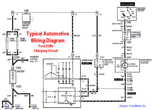
Vehicle manufacturers publish wiring diagrams for all of the various electrical circuits in the vehicles they make. These may be obtained from the Vehicle Manufacturer Technical Websites or from an automotive aftermarket source such as AlldataDIY for a small fee. Having the correct wiring diagram is an absolute must for troubleshooting electrical circuit problems.
Wiring diagrams use symbols (see below) to identify various circuit components. Individual circuits are usually numbered, and the wires in the circuits are color-coded to make identification easier. When there is a two-color code for a wire, it means the wire is one color and there is a colored stripe of a different color on that same wire.

 Related Articles:
 Click Here to See More Carley Automotive Technical Articles