 More Engine Diagnostic Articles:

Source: Illinois Air Team seminar instructor Ken Zanders
The first items you will need to verify are power and ground circuits for the DLC (Diagnostic Link Connector located under the instrument panel). You must first disable the vehicle so that it cranks but does not start. You will then perform a voltage drop check on the system ground. The use of a DLC breakout box (as shown below) is preferred for testing.

Attach one meter lead to Pin# 4 of the DLC and the other lead to battery negative with the engine cranking. Perform the same test on Pin# 5 of the DLC to battery negative as well. This is a good dynamic test that should show a voltage drop of .2 volts or less. The next test on the DLC will be to check Pin# 16 for battery voltage. You must always refer to service information to verify that you are testing the proper pins.
The next step is to check communication circuits. There are terminating resistors that are used to reduce electrical noise on these communication circuits. A review of the schematics that refer to vehicle communication for the vehicle you are working on is a valuable asset to properly diagnosing a communication issue. It is strongly recommended that a DLC breakout box be used for testing. The first test procedure is to check between Pins# 6 and 14 of the DLC with an ohmmeter. This resistance check should yield a resistance value of approximately 60 ohms. An example system diagram is shown below for review.

The next test is to check voltage information on DLC pin# 6 and 14. Pin# 6 is normally denoted as CAN-H and Pin# 14 is normally denoted as CAN-L. The voltage information can be checked with a voltmeter or lab scope. If a voltmeter is used, it is important to note that a peak min-max function should be used with a time testing window of 1ms or less.

The voltmeter cannot tell you the quality of the signal being produced. A lab scope gives a visual picture of the electrical quality of the signal that is present. A sample CAN voltage pattern on a lab scope is shown below for reference.
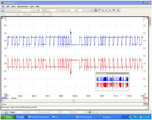
CAN H will have a voltage range of 2.5 to 3.5 volts, where as CAN L will have a range of 2.5 to 1.5 volts. The wiring on the vehicle must be checked for shorts to ground, voltage, or opens. If wires are next to each other, it is also possible for wires to be shorted to each other. In many cases, frayed wiring has contributed to lack of communication on many of the vehicles tested. It is also important to be able to attempt communication with the vehicle on the generic as well as the enhanced side. It is possible for it to communicate one way and not the other. When a vehicle is at the test facility, the communication attempt is made on the generic side. In closing, the breakout box provides a way to view the communication activity under dynamic conditions. You must always check all feeds, all grounds, and serial data to a module before any replacement is considered.
More Engine Diagnostic Articles: Click Here to read more Automotive Technical Articles
